Controls
June 2020 - September 2020
When I first joined the underwater robotics team, the robot did not have a control system. In the summer of 2018, we worked together and created a disorganized but functional control system. It, however, required that the robot remain upright to be stable. In the summer of 2019, we upgraded the system to be a little more smooth while allowing the robot to be upside down. One problem we faced with this system was gimbal lock due to the Euler angles.
The summer of 2020 came around, and we had big plans for the robot. We wanted to plan trajectories for the robot to follow and then have it follow that trajectory. The controls system at the time did not have the capability to follow trajectories, so we knew we had to change the controller. Instead of patching the old controller, we decided to create a new control system.
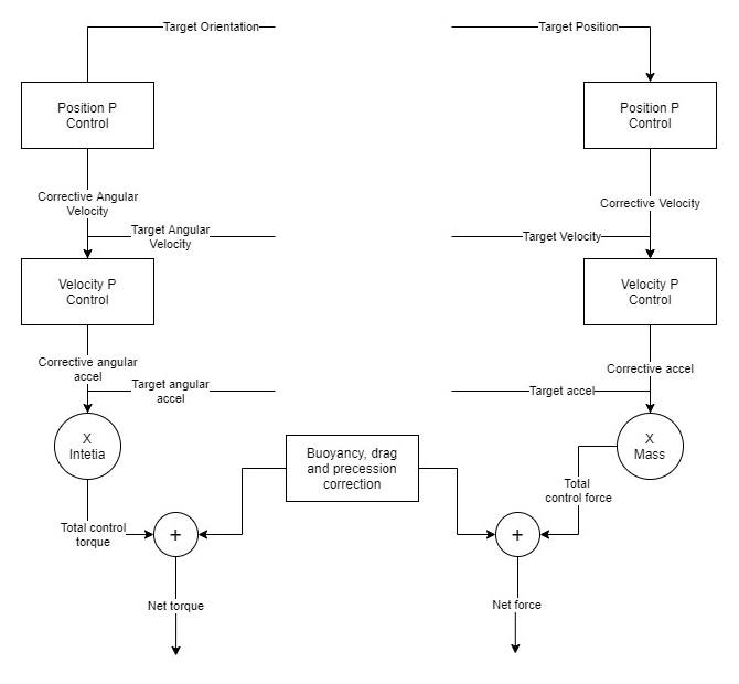
The team had already looked into LQR control but did not make much progress. Instead of trying again at LQR, the team decided to embrace a new and simpler idea so that all members could understand: cascaded PID control. The idea is to use a PID controller to control velocity by outputting acceleration to the thrusters. Then, to control position, a PID controller outputs velocity to the other PID controller. This system will speed up to drive to the target and slow down once it's near. In our specific circumstance, we could get by with only P control and no I or D term. We were using cascaded P controllers.
P controllers are not great at handling the constant forces you experience underwater such as buoyancy or drag, so we removed those effects mathematically. Whatever acceleration the P controller requested, a force would be calculated, and then buoyant force and drag added to cancel the effects. This force will then be output by the thrusters to achieve the acceleration requested. These buoyancy parameters and drag parameters were determined experimentally through the calibration code.
To follow a trajectory, one needs to feed in information about the current position, velocity, and acceleration. The controller will then fight to be at that position, have that velocity, and also output the given acceleration at that moment. The P controllers work by outputting a velocity or acceleration that adds to the target velocity or acceleration. For example, if the given velocity is 1m/s but the position is a little behind, a positive corrective velocity will be added to the 1m/s.
One of these cascaded P controllers was used for the 3 linear dimensions and one used for the angular dimensions. The math on the angular position controller was a little different due to the circular nature of quaternions. To calculate the velocity, a difference quaternion was computed and then extrapolated to angular velocity. After that, velocity differences were calculated the same as linear.
To convert body-frame forces to thruster speeds, an optimizer was used. It has all the equations of motion for how thruster forces translate to body forces. It finds the best thruster forces to output the most correct body-frame force with the least power consumed. The optimizer also knows about the max forces a thruster can output and whether or not it is submerged and can adapt as necessary.
Due to COVID, this code has not been tested on the robot but works well in simulation. It meets all the requirements it was set out to achieve.